Custom ESP8266 Relay Board with Home Assistant and ESPHome
This project came out of a need to control relays from Home Assistant for an automated garage door opener in a more secure way than a typical RF remote which can be easily spoofed, giving access to the whole house. I also wanted a solution that could be reused for other outdoor automation projects, without relying on a collection of smart plugs and adapters.
At the time, I couldn't find any product that combined an ESP8266 and multiple relays in a way that made sense for my project, so a custom PCB made the most sense.
Hardware architecture
The board is organized around three main functional blocks.
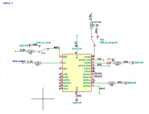
ESP8266 core
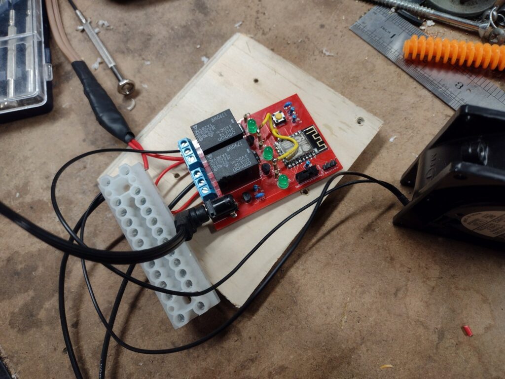
At the center of the design is an ESP-12F module (ESP8266). I’ve used this module in previous projects and I like it because it's an easy way to integrate WiFi in a prototype while hand soldering the boards. The modules are not always perfectly flat, but they can be hand soldered with a bit of effort using a hot air station.
The board includes a standard in-circuit programming header (ISP) and boot configuration switches so I can flash the firmware to the board directly using a cheap and easily available USBTinyISP adapter.
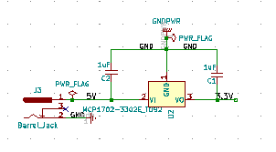
Power regulation
For power, I reused the MCP1702 regulator I’ve had good results with in other designs. It accepts input voltages from 2.7V to 13.2V and provides a stable 3.3 V output for the ESP8266.
Using a wide-input regulator means the board can be powered from a variety of supplies, including common barrel-jack adapters I already keep on hand.
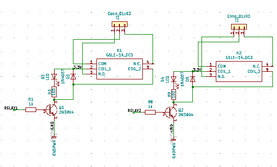
Relay driver stage
The relays are driven through a transistor as the ESP8266 GPIO pins cannot source enough current directly. Each relay block includes:
- A relay sized for up to 5A at 120VAC (the relay can take up to 10A, but not the traces).
- A transistor driver.
- A flyback diode to protect against inductive kickback.
- An indicator LED to show relay state (makes both debugging and deployment much easier).
Pin assignment constraints on ESP8266
During testing of the first PCB revision, an issue surfaced related to pin selection on the ESP8266. The two GPIOs I initially assigned to the relays are also used as flash data pins, which caused intermittent boot failures and unexpected resets.
The way it showed up was pretty random: the board would sometimes work briefly, or work with only one relay enabled.
The fix involved rerouting the relay control signals to GPIO12 and GPIO13, which are safe pins for this use according to ESPHome documentation. I cut the traces and patched the V1 prototype to validate the solution, then corrected the pinout in subsequent revisions.
I also changed the location of a few parts in the latest version since I had to rewire the relay pins anyway: I moved the barrel jack at the bottom and added mounting holes.
ESPHome integration
The firmware side is handled entirely through ESPHome. Each relay is configured in ESPHome before programming with explicit pin assignments such as:
switch:
  - platform: gpio
    name: "Board 1 relay 1"
    pin:
      number: 12
      inverted: false
  - platform: gpio
    name: "Board 1 relay 2"
    pin:
      number: 13
      inverted: false
Note: The inverted configuration allows you to set the relay to be on or off by default.
Programming is done via the in-circuit programmer with the board in "program" mode, then switched back to "run" mode for normal operation. Once flashed, each relay appears in Home Assistant as a standard switch, allowing them to be controlled like any other entity.
Full schematics, PCB layout, and parts list are available in the KiCad project on GitHub: https://github.com/CindyPotvin/WifiRelayESPHome